
Description
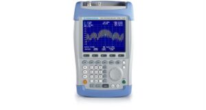
The Rohde & Schwarz FSH6 is the ideal spectrum analyzer for rapid, high-precision, cost-effective signal investigations. It provides a large number of measurement functions and so can handle anything from the installation or maintenance of a mobile radio base station up to on-site fault location in RF cables as well as development and service – an extensive range of applications.
Measurement Functions of the Rohde & Schwarz FSH6:
- Spectrum analysis
- Scalar network analysis
- Vector network analysis
- Receiver mode:
- When equipped with the R&S FSH-K3 option, the Rohde & Schwarz FSH6 can be operated as a receiver for monitoring and precompliance EMC applications. Measurements are performed at a predefined frequency with a user-selectable measurement time. In the scan mode, the Rohde & Schwarz FSH6 sequentially measures each level at various frequencies defined in a channel table. The channel tables are generated with the R&S FSH View software and loaded into the Rohde & Schwarz FSH6. For a few TV transmitter and mobile radio standards, the tables are predefined. In addition, the CISPR bandwidths 200 Hz, 9 kHz, 120 kHz, and 1 MHz are available for EMI emission measurements. The Rohde & Schwarz FSH6 offers peak, average, RMS, and quasi-peak detectors.
- Channel power measurements:
- The Rohde & Schwarz FSH6 determines the power of a definable transmission channel by means of the channel-power measurement function. A channel-power measurement for the digital mobile radio standards 3GPP WCDMA, cdmaOne, and CDMA2000® 1x is performed at a keystroke with all the correct instrument settings. With the R&S FSH View software, the user can quickly and easily define further standards and load them into the Rohde & Schwarz FSH18.
- TDMA power measurements:
- By means of the TDMA POWER function, the Rohde & Schwarz FSH18 performs time-domain power measurements within a timeslot of TDMA (time division multiple access) methods. All the settings required for the GSM and EDGE standards are predefined on the ¸FSH to make these measurements easier for the user. In addition, up to five user-definable instrument setups can be loaded into the Rohde & Schwarz FSH6 using the R&S FSH View software.
- DTF (Distance to fault) Measurements on Cables:
- The R&S FSH-B1 option allows the distance to any faults in an RF cable to be determined rapidly and accurately. Distance-to-fault measurements using the R&S FSH-Z2/-Z3 VSWR bridge provide an immediate overview of the state of the device under test (return loss and distance, see figure). The marker-zoom function allows detailed analysis of faults with a resolution of up to 1024 pixel.
- 3GPP FDD code domain power measurements on base stations:
- The R&S FSH-K4 option1) allows code domain power measurements on a 3GPP base station. It measures the total power and the power of the most important code channels, such as the common pilot channel (CPICH), primary common control physical channel (P-CCPCH), primary synchronization channel (P-SCH), and secondary synchronization channel (S-SCH). Furthermore, the carrier frequency offset and the error vector magnitude (EVM) are measured and displayed. The scrambling code can be determined at the press of a button and used automatically for decoding the code channels. The user can also get a quick overview of adjacent base stations. The R&S FSH6 can display up to eight scrambling codes with their CPICH power. The R&S FSH-K4 option provides automatic level setting for fast and optimal setting of the reference level. In practice, this means very easy operation. To display the code domain power measurement values, only four operating steps are necessary:
- Select the 3GPP CDP function
- Set the center frequency
- Use “Level Adjust“ to optimize the level setting
- Start the scrambling code search
- For base stations with two antennas, the user can select which antenna the R&S FSH should synchronize to (antenna diversity).
- The R&S FSH-K4 option1) allows code domain power measurements on a 3GPP base station. It measures the total power and the power of the most important code channels, such as the common pilot channel (CPICH), primary common control physical channel (P-CCPCH), primary synchronization channel (P-SCH), and secondary synchronization channel (S-SCH). Furthermore, the carrier frequency offset and the error vector magnitude (EVM) are measured and displayed. The scrambling code can be determined at the press of a button and used automatically for decoding the code channels. The user can also get a quick overview of adjacent base stations. The R&S FSH6 can display up to eight scrambling codes with their CPICH power. The R&S FSH-K4 option provides automatic level setting for fast and optimal setting of the reference level. In practice, this means very easy operation. To display the code domain power measurement values, only four operating steps are necessary:
- Field strength measurements:
- When measuring electric field strength, the Rohde & Schwarz FSH6 takes into account the specific antenna factors of the connected antenna. Field strength is displayed directly in dBμV/m. If W/m2 is selected, the power flux density is calculated and displayed. In addition, frequency-dependent loss or gain of, for example, a cable or an amplifier can be corrected. For quick and easy result analysis, the Rohde & Schwarz FSH6 provides two user-definable limit lines with automatic limit monitoring.
- Isotropic antenna measurements:
- When used with the R&S TS-EMF isotropic antenna, the Rohde & Schwarz FSH6 can determine the direction-independent resultant field strength in the frequency range from 30 MHz to 3 GHz. For measuring the resultant field strength, the antenna has three orthogonal antenna elements. The Rohde & Schwarz FSH6 successively triggers the three antenna elements and calculates the resultant field strength. The calculation takes into account the antenna factors for each individual antenna element as well as the cable loss of the connecting cable.
- C/N measurements:
- The Rohde & Schwarz FSH6 offers a carrier/noise (C/N) measurement for determining the ratio of carrier power to noise power or carrier power to noise power density. The Rohde & Schwarz FSH18 supports three different modes for carrier power measurement. In the CW TX mode, the Rohde & Schwarz FSH6 determines the power of an unmodulated carrier. In the digital TX mode, it determines the channel power of a reference channel, as is common with digitally modulated carriers (e.g. the DAB, DVB, DVB-T, DVB-H, and J.83/A/B/C standards). Furthermore, the ATSC standard for digital terrestrial television with 8VSB modulation is supported. In the analog TV mode, the Rohde & Schwarz FSH6 measures the peak power of the vision carrier with amplitude-modulated TV signals.
- Power measurements:
- The R&S FSH-Z1 and R&S FSH-Z18 power sensors expand the Rohde & Schwarz FSH18 to a high-precision RF power meter up to 8 GHz and 18 GHz respectively. As with thermal sensors, the true RMS value of the measured signal is obtained over the entire measurement range of –67 dBm to +23 dBm irrespective of the signal waveform. In particular with modulated signals, additional measurement errors can thus be prevented, and handling becomes easy.
- Directional power measurements:
- The R&S FSH-Z14 and R&S FSH-Z44 directional power sensors turn the Rohde & Schwarz FSH6 into a full-fledged directional power meter with a frequency range of 25 MHz to 1 GHz and 200 MHz to 4 GHz. The Rohde & Schwarz FSH6 can then simultaneously measure the output power and the matching of transmitter system antennas under operating conditions. The power sensors measure average power up to 120 W and normally eliminate the need for any extra attenuators. They are compatible with the common standards GSM/EDGE, 3GPP WCDMA, cdmaOne, CDMA2000® 1x, DVB-T, and DAB. Additionally, the peak envelope power (PEP) can be determined up to a maximum of 300 W.
- Channel Tables
- If preferred, the R&S FSH can be tuned by channel numbers rather than by entering the frequency. The channel number is displayed instead of the center frequency. Users who are accustomed to channel assignments, which are common in TV and mobile radio applications, can operate the R&S FSH more easily. The channel tables are generated with the R&S FSH View software and loaded into the R&S FSH. The R&S FSH includes TV channel tables for a number of countries
- Scalar transmission and reflection measurements with VSWR bridge:
- The Rohde & Schwarz FSH18 with built-in tracking generator rapidly determines the transmission characteristics of cables, filters, amplifiers, etc, with a minimum of effort. When equipped with the R&S FSH-Z2/-Z3 VSWR bridge (10 MHz to 3 GHz/6 GHz), the Rohde & Schwarz FSH6 can also measure the matching (return loss, reflection coefficient, or VSWR) of an antenna, for example. The bridge is screwconnected directly to the Rohde & Schwarz FSH18’s RF input and tracking generator output without involving cumbersome, extra cabling. The innovative design of the R&S FSH-Z3 VSWR bridge with integrated RF bypass switch allows the user to make spectrum and transmission measurements also with the bridge connected. Active components such as amplifiers can be supplied directly via the RF cable by means of the two integrated bias tees.
- Vector transmission and reflection measurements:
- Compared to scalar transmission and reflection measurements, the R&S FSHK2 option offers a significant increase in measurement accuracy and number of measurement functions. In addition to the magnitude of S11 and S21, the phase, group delay, and electrical length of a DUT can be determined. The Smith chart allows simultaneous display of magnitude and phase in order to analyze the matching of an antenna in detail, for example. A user-definable limit line and a zoom function come in handy when evaluating the measurement results. Owing to a wide variety of marker formats, the measured values are displayed in virtually all the conventional formats used in network analysis. The input of a reference impedance permits measurements on DUTs whose impedance is not 50 Ω. To increase measurement accuracy, the Rohde & Schwarz FSH6 performs complex correction of the system errors after calibration.
- Locating EMC weak spots:
- The R&S HZ-15 near-field probe set is a diagnostic tool for locating EMC weak spots on printed boards, integrated circuits, cables, shieldings, and other trouble spots. The R&S HZ-15 near-field probe set can handle emission measurements from 30 MHz to 3 GHz. Its sensitivity can be enhanced by adding the R&S HZ-16 preamplifier, which has a frequency range of up to 3 GHz, a gain of approx. 20 dB, and a noise figure of 4.5 dB. In combination with the Rohde & Schwarz FSH6, the preamplifier and near-field probe set are a cost-effective means of analyzing and locating sources of interference during development.
- One-port cable loss measurements:
- The Rohde & Schwarz FSH6 with tracking generator and VSWR bridge can determine the cable loss of previously installed long cables without much effort. One end of
the cable is connected to the VSWR bridge, and the other end is terminatedwith a short circuit or simply left open. The calculated cable loss represents the average value within the displayed frequency range. The loss at specific frequencies is determined via markers. The one-port cable loss measurement is only available with the R&S FSH-K2 option.
- The Rohde & Schwarz FSH6 with tracking generator and VSWR bridge can determine the cable loss of previously installed long cables without much effort. One end of
Contact TestWorld for pricing on a used/refurbished Rohde & Schwarz FSH6 6 GHz Handheld Spectrum Analyzer – Rental and Leasing options available.